Showing posts with label Pump. Show all posts

Jan 15, 2023

Centrifugal Pump Parts, Working, Advantages and Disadvantages

What is Centrifugal pump? centrifugal pump is one which uses the centrifugal force to pump up the water to a certain head. 

This type of pump first rotate water using its impeller and then the that rotational motion push water out with a great force.

This force out going water is due to the centrifugal force of rotating water. Centrifugal force try to trough water away in a direction tangent to the water circular motion.

Centrifugal pump have some certain advantages over reciprocating pump. So we have created this comprehensive article about it. 


Centrifugal Pump Diagram

Classification or Types of Centrifugal Pump

Following is division of types of centrifugal pump

1. Type of casing

2. Working head 

3. Liquid handled

4. Number of impellers per shaft

5. Number of entrances to the impeller

6. Relative direction of flow through impeller

1. Type of casing

According to the type of casing centrifugal pump have two basic types

1.1 Volute casing

In order to increase the pressure head, the velocity of water is decrease. It is done by gradually increasing the area of the casing from the impeller out let

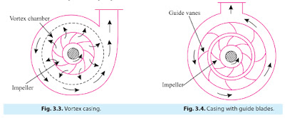
1.2 Vortex Casing

If a circular chamber known as vortex is introduce between the impeller and chamber then the casing is called vortex casing . Its main function is to convert the kinetic energy into pressure energy

2. Working head 

Each pump can pump up a water to a certain height so following are the types of centrifugal pump according to the working head

2.1 Low lift centrifugal pump   

2.2 Medium lift centrifugal pumps

2.3 High lift centrifugal pumps

Low lift centrifugal pump are capable of working against heads up to 15 m. Medium lift centrifugal pump are basically used against the heads as high as 40 m and High lift centrifugal pumps are used to deliver liquids at heads above 40 m.

3. Liquid handled

According to the type of liquid pumped centrifugal pump is classified into three types

3.1 Pure liquid

When pure liquid is to pumped the centrifugal pump with the closed impeller are used because they have better guidance and high efficiency

3.2 Little impure liquid

When liquid have a little impurity then centrifugal pump with semi open impeller are used

3.3 Liquid with solid matter

When sewage, paper pulp, water containing sand or grit is to be pumped then pump with open impeller is used.

4. Number of impellers per shaft

There are various numbers of impeller that can be diploid on the shaft of a pump and following are the classification based on the number of pumps

4.1 Single stage centrifugal pump

Single stage centrifugal pump is one which has only one impeller attached to the shaft. they are used in place where low head and low discharge rate is required

4.2 Multi-stage centrifugal pump

 Multi-stage centrifugal pump is one which has more then one impeller attached to a single shaft. they are used in place where high head and high discharge is required

5. Number of entrances to the impeller

Usually it is consider that pump have only one entrance and one leaving point but there could be more than one and following is classification base upon number of entrances a pump have

1. Single entry or single suction pump

2. Double entry or double suction pump

Single entry also called single suction pump is one in which water is admitted on one side of the impeller. 

Double entry or you can say double suction pump is one in which water is admitted on both sides of the impeller; axial thrust is neutralized. They are usually employed for pumping large quantities of water.

6. Relative direction of flow through impeller

Depending upon the direction of the liquid flow centrifugal pump can be classified as follow

1. Radial flow pump

2. Axial flow pump

3. Mixed flow pump

Radial flow pump are one in which regular radial flow impellers are used. Axial flow pump are one in which designed to deliver low head but huge quantity of water. Mixed flow pump are mostly used for irrigation purpose


Centrifugal Pump Parts

We will discuss the centrifugal pump parts by starting from suction of water and will end at delivery of water at reservoir. So parts of centrifugal pumps are as follow.

Suction Side Parts of Centrifugal Pump

Starting the discussion on parts of a centrifugal pump from section side of the pump is important. As most of the important and crucial parts of centrifugal pump are on suction side.

Suction pipe

Pipe which lifts the liquid from the sump and provides it to the pump at the impeller eye is called suction pipe. Suction is made air tight in order to stop the formation of air pocket with in the pump

Strainer

A strainer is attached at that end of the suction pipe which is dipped into the sump. Its main function is to stop the solid particle from entry into the pipe

Foot valve

Just above the strainer there is afoot valve whose function is to prevent the back flow of water when pump is stopped. It is also priming of pump

Impeller

It is just like a wheel with a few number of vanes attached to it. It is mounted on to a shaft which is rotated by an electric motor. There are three main types of impellers used by the centrifugal pump.

Shrouded or closed impeller

Impeller type is which there are vanes with metal cover or vanes with shrouds ends. They have an advantages that they have better guidance and high efficiency but there is one limitation that should be clean and pure

Semi open impeller

In this type of impeller vanes have no crown plates and only have a base plate they have an advantages a over closed impeller that they can pump liquid with little impurities. 

Open impeller

In this type of impeller vanes are open from both sides or you can say that they are lacking base plate and crown plate. Their advantages is that they can pump sewerage water, paper pulp and other impure liquid with suspended particles

centrifugal pump diagram . jpge
centrifugal pump impeller diagram

Casing

Impeller of the pump is surrounded by the air tight metal chamber called pump casing. Arrangement is made on casing for the attachment of the suction and delivery pipe. It function is to guide the incoming water toward the impeller and take high kinetic energy water from impeller. Its other function is to convert the kinetic energy of the water into the pressure energy

There are three basic types of casing in centrifugal pump

  1. Volute casing
  2. Vortex casing
  3. Casing with guide blades

centrifugal pump diagram . jpge
centrifugal pump diagram

Delivery side parts of Centrifugal Pump

Discussing the water delivery side parts of centrifugal pump is also important. They are less in number but are equally important as suction side centrifugal pump parts

Delivery pipe 

Pipe which takes the high pressure liquid from the pump and deliver it to the reservoir is called delivery pipe

Delivery valve

Delivery valve is provided at the delivery pipe near the attachment point of pipe and pump. It is use for priming and stopping the back flow of liquid.


Working of  Centrifugal Pump

Centrifugal pump work on the principle of centrifugal force.  Centrifugal force in one is tried to take away a rotating body from its center of rotation. 

In centrifugal pump when a liquid is rotated by the impellers of pump then centrifugal force created will draw away the rotating liquid from the central axis and so a centrifugal head is created which enable the liquid to rise up to a certain level.

Step by step working of centrifugal is given below

Priming of pump

Filling of pump with water so that no air pocket is left in pump is called priming of pump. Priming is done by closing the delivery pipe and fills the whole pump (that is casing, delivery pipe up to valve and suction pipe) with water.

Creating strong suction

A strong suction is needed to start the suction of the liquid from the source. For this purpose delivery valve is kept close and pump is started. Rotating impeller will create a strong suction or vacuum at the eye of impeller.

Creating the normal pressure

Rotation speed of the impeller is increase with the delivery valve closed until it attains a normal speed. With this speed pump establish a normal pressure required to start pumping

Suction of liquid 

When pump establish a normal pressure then delivery valve is opened and liquid is sucked into suction pipe and enter into casting through the impeller eye. In casting rotating impeller rotate the liquid and thus create the centrifugal force needed to create the centrifugal head

Delivery

When liquid in the casing attains a specific centrifugal force it is pushed into the delivery pipe and taken to a specific height due to centrifugal head

Continuous process

As long as the impeller of the pump continuous to rotate there will be a suction pressure at inlet and centrifugal head at outlet and the liquid will be transfer from source to reservoir

Closing the pump

When you need to close the pump, first the delivery valve is closed and then impeller should stop rotation. Otherwise there will be some back flow from reservoir 

Like every thing else centrifugal pump has their own advantages and disadvantages. 


Advantages and Disadvantages of centrifugal pump

Follow are the advantages and disadvantages of centrifugal pump

Advantages of centrifugal pump

  • As there is no drive seal so there is no leakage in pump
  • It can pump hazardous liquids
  • There are very less frictional losses
  • There in almost no noise
  • Pump has almost have 100 efficiency
  • Centrifugal pump have minimum wear with respect to others
  • There is a gap between pump chamber and motor, so there is no heat transfer between them
  • Because of the gap between pump chamber and motor, water cannot enter into motor
  • Centrifugal pump use magnetic coupling which breakup on high load eliminating the risk of damaging the motor

Disadvantages of centrifugal pump

  • Because of the magnetic resistance in centrifugal pump there is some energy losses
  • Unexpected heavy load may cause the coupling to slip
  • ferrous particles in liquid are problematic when you are using magnetic drive. 
  • This is because particle collect at centrifugal pump impeller and cause the stoppage of pump after some time


Centrifugal pump vs Positive Displacement pump or Reciprocating pump

There are two main types to pumps available 

1. Centrifugal pump

2. Reciprocating pump

The centrifugal pump claims to have following advantages over positive displacement pump. So here is over positive displacement pump vs centrifugal pump section.

1. Because of fewer parts centrifugal pump have less cost than reciprocating pump

2. Also because of fewer parts installation and maintenance are easier and cheaper as compared to reciprocating pump

3. Centrifugal pump have much greater discharging capacity than reciprocating pump

4. Centrifugal pump is compact and small in size and have less weight for the same capacity and energy transfer as compared to reciprocating pump

5. Centrifugal pump performance  characteristics are superior as compared to reciprocating pump

6. Centrifugal pump can be used for lifting highly viscous liquid such as paper pulp, muddy and sewage water sugar molasses and oil but reciprocating pump cannot do that

7. Centrifugal pump can be used at high speed without the danger of separation and cavitation whereas reciprocating pump has a danger of separation and cavitation

8. Centrifugal pump can be directly coupled to an oil engine or electric motor whereas reciprocating pump lack this property

9. The torque on the power source is uniform, the output from the pump is also uniform

However, the reciprocating pump have higher efficiency than centrifugal pump and that's why they are still employed for uniform heads and small discharges. 

A reciprocating pump has the ability to producing very high pressure as compared to centrifugal and so that’s why they are used for lifting oils from very deep oil wells. 

Jan 14, 2023

What is Reciprocating Pump: types, Parts, Working, Advantages, and Disadvantages

What is reciprocating pump? its a one of the most common type of pump used for all types of applications including domestic water pump. 

A reciprocating pump is one that move water due to the reciprocating (forward and backward action) motion of its piston. 

Piston moves back and pump suck in water from its source and as piston move forward the pump pushes the water out with great force and pressure.

Types of Reciprocating Pump

Follow are the three fields in which the reciprocating are classified

1. According to the contact between water and plunger

2. According to the number of cylinders

3. According to the air vessel

According to the contact between water and plunger

Single acting pump

A single acting pump is one which has one suction valve, delivery valve and one suction and delivery pipe. It suck up the fluid only in one direction and in single stroke called  suction stroke and deliver it in a single stroke called delivery stroke

Single acting reciprocating pump

Double acting pump

A double acting pump is one which has two suction valves, delivery valves and two suction and delivery pipes. If we suppose that piston is in the center of the cylinder then one suction and delivery pipe is on one side and one delivery and suction pipe is on other side of the piston.

double acting reciprocating pump

According to the number of cylinders

1. Single cylinder pump

Single cylinder pump is one in which their is only cylinder connected to a single shaft. It could be a single acting or double acting pump.

2. Double cylinder pump

Double cylinder pump is one which have two cylinder attached to a single shaft. Separate suction and delivery valve is provided to each cylinder. Crank of the pump is set at an angle of 180 

3. Triple cylinder pump

When the pump has three cylinders attached to a single shaft then the pump is called triple cylinder pump. Crank is set at an angle of 120

According to the air vessel

1. With air vessel

Some reciprocating pump are provided with a separate air vessel attached to the suction and delivery valve. Its main function is to accumulate excess quantity of water by compressing the air in the vessel

2. With out Air vessel

Some pump lack the air vessel because of the nature of their work. for example the reciprocating boiler feed pumps does not have air vessel because they may introduce air into the deairated water


Parts of reciprocating pump 

Parts of reciprocating pump with their details are as follow

Crank

Crank is a circular disk attached to the motor and used to transfer the rotation motion of the motor to the piston

Connecting rod

Connecting rod is the long solid rod. It provide connection between crank and the piston. It also convert the rotation motion of crank into the linear motion of the piston.

Piston  

Piston is the solid cylinder like part of the pump which moves linearly in the hollow cylinder of the pump. It motion is main reason behind suction and deliverance of the liquid


Components of reciprocating pump . jpge
Components of reciprocating pump

Cylinder

It is a hollow cylinder in which piston moves. Suction and deliverance take place with in it. Suction and delivery pipe and valves are attached to its one end piston come and go back from other end.

Suction pipe

Pipe which take liquid from the source and provide it to the cylinder of the pump  is called suction pump

Suction valve

It is one way valve place between suction pipe and cylinder of the pump. It is open when suction take place and close when delivery of the water is taking place

Delivery pipe

Pipe which take water from the cylinder of the pump and provide it to the tank is called delivery  pipe.

Delivery valve

It is one away vale and placed at the point of attachment of delivery pipe with cylinder. It is open when delivery of water is taking place and closed when suction of water in taking place

Strainer

It is a filter like parts provided at the end of suction pipe. Its main function is to stop is solid particles from entering into the pipe

Air vessel

Installed at the suction and delivery pipe and its main function is to give a steady flow by reducing the frictional head 


Working of Reciprocating Pump

Now we will discuss the working of two basic types of reciprocating 

  • single acting reciprocating pump 
  • double acting reciprocating pump

Working of Single acting reciprocating pump

Suction

Let us suppose that the pump piston is at the inner dead centre and the crank start to rotate in the clock wise direction. As the crank start to rotate piston start to move toward the outer dead centre. 

As the piston moves back vacuum is created and force the suction valve to open and suck up the water from the sump into the cylinder of the pump

Single acting reciprocating pump

Delivery

Now after the suction process is complete, piston of the pump is at the outer dead centre. As crank continuous to rotate the piston of the pump is now force to move toward the inner dead centre and in doing so piston force the water and creates the pressure inside the pump and as the pressure reached a specific value delivery valve is open and water is transfer to the tank.

Working of Double acting reciprocating pump

Piston moving in right direction

let us suppose that the piston is initially at the centre of the cylinder and crank start to rotate on clock wise direction so the piston will move toward the right side and thus vacuum is created at left side of the piston and pressure is created at the right side of the piston. 

Vacuum at left side force the water to move into the cylinder from the sump and pressure at the right force the water to move up from the delivery pipe in to the tank

Double acting reciprocating pump . jpge

Piston moving in left direction

As the crank continuou to rotate, piston after reaching at one end now moves is left direction and so pressure is created at the left side of the piston and vacuum is created on the right side of the pump. Vacuum cause the water to move up in the pump and pressure cause the water in pump to move into the tank.

Advantages and Disadvantages of Centrifugal Pump

Following are the advantages and disadvantages of reciprocating pump

Advantages of reciprocating pump

  • High efficiency
  • No priming needed
  • Can deliver water at high pressure
  • Can work in wide pressure range
  • Continuous rate of discharge

Disadvantages of reciprocating pump

  • More parts mean high initial cost
  • High maintenance cost
  • No uniform torque
  • Low discharging capacity
  • Pulsating flow
  • Difficult to pump viscous fluid
  • High wear in parts

Oct 19, 2021

Gear Pump: Working, Types, Application, Advantages and Disadvantages

The pumps have become a most vital part of all household, industrial, and many other applications. They are most widely used all over the world. 

There are multiple types of pumps according to the requirements of different applications like gear pump, piston pump, centrifugal pump, reciprocating pump. 

The gear pump is the most widely used pump.  The name of this pump represents that it uses gears for operation. 

In simple words, the gear pump transfers fluid from one place to another by using gears. 

These gears use to deliver force to move the water inside the pump. This article gives you an overview of the gear pump. We, therefore, explain to you an overview of the different types, working principle, applications, advantages, and disadvantages of these pumps.

Must read: Piston Pump Explained

What is a Gear Pump?

The gear pump is the most common positive displacement pump (PD). This pump moves the water by using a series of gears. 

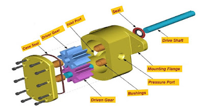
These gears are named driver gear and driven gear. These gears are meshed with each other. The main objective of the driver gear is to drive the driven gear. This driver gear connects with a shaft.

The shaft gets power from an electric motor or generator and delivers this power to the driver gear.  

The gear pump provides a smooth pulsation-free flow which is proportional to the gear speed.  

Working of Gear Pump

A gear pump operates on the positive displacement principle.  It uses gears to pump the water. A gear pump works in the following way:
  • Firstly, the power is delivered from the electric motor to the shaft.
  • When the shaft rotates, it further transfers its rotation to the driver gear.
  • The driver gear further moves the driven gear, which is meshed with the driver.
  • Due to the rotation of these gears, a vacuum generates inside the pump due to that water starts to enter the pump. During this process, the inlet valve opens, and the discharge valve remains close.
  • As the suction process, the inlet valve also closes, and water is trapped between the gears because there is no direct way for the water to go into the discharge valve.
  • After this process, the drive and driven gears move together. With the movement of these gears, the trapped water slowly flows toward the discharge valve. 
  • In this way, the water is pressurized and delivered up to the desired area.


Gear Pump Part . jpge
Gear Pump Part

Different Types of Gear Pumps

The gear pumps have the following two most common types:
  • External Gear Pumps
  • Internal Gear Pumps

External Gear Pump

It has two gears, the idler or driver gear, and driven gears. The idler gear connects with a shaft. Some gear pumps don't have a shaft. 

In such cases, the gear is directly connected with the power source (i.e., electric motor). However, if the pump has a shaft, then the shaft connects with the motor, and one end of this shaft links with the idler or driver gear. 

When the gear idler and driven gears leave some space on the suction side, the cavity generates inside the pump.  

As the gear continues to rotate alongside the pump housing, fluid enters the cavity and is imprisoned between the teethes of the gears.

This imprisoned fluid can migrate from the duction end to the discharge end in the housing area.

As the area between the teeth of the gears decreases on the discharge side, the fluid area also reduces due to its pressure incases. 

Due to the high pressure of the fluid, the pump forces the fluid to be discharged. No fluid can move backward from the discharge side because the gears mesh very tightly.

Due to the close tolerance between the gears and the cover, the pump increases the suction power at the inlet and prevents liquid from escaping from the discharge end. 

The external gear pumps have the capability to use herringbone, spur, spur, or helical gears.

Advantages of External Gear Pump

  • These have a simple design
  • They have the capability to transfer a high amount of fluids.
  • They have the capability to manage the pressure (i.e., high, medium, and low) according to the requirements.

Internal Gear Pump

Internal gear pumps work similarly to the external gear pumps, but the gears of the internal gear pump have different sizes. It has a large rotor gear that has teeth on the inward side. 

Since the second external gear is mainly installed and connected with the rotor so that the teeth of the gears can connect at one end. 

The bushings and pinions can connect with the housing of the pump, which holds the idler gear in its position.

A permanent semicircular divider or spacer seals the gap formed by the eccentric mounting position of the idler gear and acts as a seal between the inlet and outlet openings. 

As the gears lose their teeth meshing on the inlet side, the cavity produces on the inlet side. As the gear continues to rotate alongside the pump housing, liquid enters the cavity and is trapped by the gear teeth. 

By connecting the teeth to the discharge surface of the pump, you can reduce the volume and use force to push the liquid out. The internal gear pump only uses spur gears.

Gear Pump Advantages and Disadvantages

Advantages of Gear Pumps

Disadvantages of Gear Pump

Gear Pump Applications

  • The gear pump is used in lube oil, crude oil, diesel oil and pitch applications.
  • They are also used to transfer isocyanates, mixed chemicals, acids, plastics, and Sodium silicate.
  • The also use to pump sludge, latex, lime, kaolin, black liquor, ink, lye, soap, and paints.
  • These pumps use in sugar, fillers, cacao butter, adhesives and resigns applications.  

Sep 6, 2021

Piston Pump: working, parts, application, advantages and disadvantages

A pump is a device which uses to deliver different fluids from one area to other. The pumps are most common all over the world, and they have become a compulsory part of all industries. 

There are multiple types of pumps like gear pump, piston pump, centrifugal pump, reciprocating pump. A piston pump is a favorite type of pump from the category of reciprocating pump. 

In this article, we will mainly discuss different aspects of the piston pump.

What is a Piston Pump?

A pump that uses a piston to deliver the fluid from one place to another place is known as a piston pump. A piston pump has a piston that reciprocates inside the compression cylinder. 

This positive displacement pump has an exterior diameter seal with a piston rod connection. It creates pressure by supplying energy to the liquid being pumped. 

This process increases the pressure of the liquid according to requirements. 

The piston pump is best for applications that need lower pressures and higher flow rates because it can drain fluids quickly and easily. You can also clean the surface with a piston pump.

Working of Piston Pump

  • A piston pump works by moving the piston up and down inside the pump cylinder. A piston pump works in the following way:
  •  A piston is linked with a shaft that further connects with an electric motor or generator.
  • As the electric motor delivers power to the shaft, it turns the piston which starts reciprocating inside the cylinder.
  • As the piston moves downward, a vacuum creates inside the cylinder.
  • Due to the creation of a vacuum, the pressure inside the cylinder becomes lower than the pressure of the atmosphere or tank.
  • Due to this pressure difference, the inlet valve opens, and water starts to enter the cylinder. During this process, the discharge valve remains close.
  • As the fluid sucks according to requirements, the inlet valve closes, and the piston starts its upward stroke.  
  • As the piston moves up (from BDC to TDC), it increases the pressure of the water by reducing the volume of the cylinder. 
  • As the cylinder's inner water pressure becomes higher than the external pressure, the outlet valve opens, and water is discharged through a discharge valve.
  • In this way, the water or other fluid is delivered to the desired location.  


Piston Pump . jpge
piston pump


Also read: Working of centrifugal pump


Types of Piston Pumps

The piston pumps have the following major types:

1) Axial piston pumps

These pumps have multiple pistons (usually odd numbers) settled in a circular arrangement within a casing known as a barrel, rotor, or cylinder block. 

This block drives to rotate about an axis of symmetry by an integrated shaft that is roughly aligned with the pumping piston.

The axial piston pump uses to power the hydraulics of jet aircraft powered by the main shaft of a turbine engine and is typically depleted in an automotive air conditioning compressor to cool the cabin. 

These pumps are designed to meet the restricted space and weight requirements of the automobile's engine compartment and to reduce vibration.

The axial reciprocating motors also use to power small civil engineering machinery like skid loader machines. 

2) Radial Pump

The radial pump contains a sequence of pistons in a cylindrical block that surrounds the rotor hub. This block has a rotor, a barrel with a piston, and a shaft. 

The rotor moves the fluid in and out of the cylinder. The rotor attaches in an eccentric position inside the casing of the pump. 

This rotor also helps the piston to move upward and downward inside the cylinder. 

During this motion of the piston, the hydraulic oil is sucked into the cavity of the cylinder and leaves the pump from it. 

The pump suction and discharge valves are installed on the central hub. 

Each piston connects to the suction valve when it begins to expand and to the discharge valve when it contracts.

These types of pumps supply power to a liquid system by forcing the liquid flow outward. They have high efficiency and reliability. 

They have the capability to a high amount of pressure. Therefore, they are used in different types of industrial applications, such as power generation, machinery, and rig testing.

3) Lift or Suction Pump

In this type of piston pump, the upward piston stroke sucks fluid through the valve to the bottom section of the cylinder. 

In the piston's downward stroke, fluid passes through the valve and enters the cylinder's upper section. 

In the next upward stroke, the piston will discharge the fluid from the upper of the cylinder through a nozzle. 

With this type of pump, the air pressure is restricted through the height of the fluid that can withstand the vacuum.

4) Inline Pump

These reciprocating pumps have very high efficiency.  The inline pump is best for regulating high flow liquid and water pressure. 

It works in the similar way as the bent axis pump but with less rotation capacity. 

However, it is a reliable axial piston pump suitable for various applications because it can generate adequate pressure.

Advantages of Piston Pumps

1. These pumps have the capacity to achieve high pressure.

2. These have the capability to transfer abrasives.

3. The piston pumps can also transfer slurries and viscous fluids.

4. These don’t have cavitation problems.

5. They don’t require initial priming.

Disadvantages of Piston Pumps

1. These pumps deliver pulsating flow.

2. The piston pump has a high design.

3. They are bulky.

4. They require high costs for maintenance and initial installation. 

5. These types of reciprocating pumps can only handle low flow rates.


Must read:  Advantages and Disadvantages of Reciprocating Pump


Applications of Piston Pump 

• Hydraulic Pressure Testing

• High-Pressure Cleaning

• Biotechnology

• Water Injection

• Water Hydraulics

• Waterjet Cutting

• Oil Hydraulics

• Drilling Service

• Descaling

• Process Technology

• Energy Saving Fluid Transportation

• Metering Systems

• Fracking


Author Bio

Myself Engineer Waqar and I am a blogger by passion. I did mechanical engineering and Mechanical Boost is my website. I am blogging from 1 year and I have good experience in this field.

Jun 30, 2021

Practical Designs, Numerical, Analytical and Experimental Studies of Tesla Turbine

Numerical and Analytical studies of Tesla Turbine

Many analytical and numerical attempts by various investigators were made during mid-nineteenth century to describe behavior of turbulent and laminar flow areas for flow between the tesla turbine’s disks. At times, computational tool capability was very limited that is why most of their studies had to rely on simple flow assumptions. Prof. W. Rice is one of the investigators who by employing different set of formulations has made his great efforts in describing and making a mathematical model of characteristics of operation and summation of parameters of multi-disk turbo machinery. He published an article in 1963 for the selection of quantity of disks of air-based friction compressors & pumps based on an incompressible and steady state flow in single inter-disk space by the determination of surface force and solution of the respective motion equations in tangential and radial coordinates. This study established the higher limit on parameters of performance like efficiency and total non-dimensional pressure rise of the pump by allocating losses due to friction to happen only among the disk spaces (i.e. entry & exit losses, wind age losses, housing and bearing are neglected). As the study continues, several derivations have been performed as for pumps in reverse operation (Multi disk Tesla Turbine) in 1965 having identical flow considerations.  It has been derived from the results of study that maximum level of pressure drop and efficiency of turbine is obtained at the inner fluid exit recess and as non-dimensional parameter of flow (Q/ωro 3) increases, the tendency of efficiency decreases. There are some other studies by W. Rice (1968). 

Many studies by Hasinger (1963) have elaborated pressure losses of different types which occur at the numerous points of the turbo machines. On the basis of previous studies for maximum attainable efficiency and power by W. Rice and his associates the existing knowledge gap in calculation of accurate performance characteristics of the device was filled by the determination of different frictional losses.  The swept path of spiral fluid particle travelling from fluid inlet of rotor to exhaust has been analytically traced out by (Jeffery, 1990). Some other investigators have also achieved the same goal by the use of other tools commercial CFD packages (Jedrzejewski, 2011) and (Piotr, 2009). Various solutions using two dimensional incompressible flow approaches have been proposed by different investigators for solving equations about various flow quantities like Reynolds number, regional shear force, tangential and radial components of velocity, pressure drop as compared with inlet conditions, flow paths of particle, etc. (Waren, 1965). Soo, (1957) has used first and second order approximation to Reynolds number for calculating the axial and radial velocity profiles of incompressible fluid flowing from a stationary and the other rotating disk plates for radially outward and inward flows. Some investigators have also tried to approach analytically by some other means such as by using numerical methods: Breiter and Pohlhausen (1962) presented calculation of outward radial flow between co-rotating disks using finite difference scheme. Boyd and Rice copied the same method for calculating radially inward flow. He modeled inlet region of turbine that grow an asymptotic flow for large Reynolds number.

Practical Designs and Experimental Studies of Tesla Turbine

N. Tesla is the person who has conducted the experiments and gave his undertakings. He conducted his experiments from 1906 to 1914 on turbine to check and investigate behavior of turbine for several different working conditions. According to him the turbines can be more than 95 % efficient exceeding conventional turbo machines of the day. He wanted to introduce a more reliable and efficient combustion engine in replacement of piston cylinder combustion engine using his technology. In their conversion of fuel to work the best available engines were not able to give more than 27 to 28 percentage efficiency. In 1966, a 6 inch wind turbine was tested by varying different conditions such as supply pressure varying from 6895Pa to 27,579 Pa, angular velocity varying from 4,000rmp to 18,000rpm and design variable such as disk spacing. He came up with observation that steam turbine with specific speed of 0.1 rpm is more efficient and give around 40-45% efficiency if it is compared with single stage turbine of same specific speed that gives efficiency up to 24% maximum. He also established a robust relation between flow rate and torque applied on disk of rotor of Tesla Turbine due to decrease in tangential velocity. 

Prof Warren Rice, in 1965, rechecked performance merit stated by tesla. For this he conducted number of experiments. Visco- Geometric properties were replicated under which preceding steps were made. His test results confirm that turbine can be operated at nearly pure impulse to solely reactive mode and the deviation of the results from N. Tesla’s claim of turbine merits at various speed , flow rate and geometry combinations. Adam (1970) tried to verify the research provided by Boyd and Rice (1968). He observed patterns of pressure drops in radial direction from inlet to outlet with partial flow admission for a narrowly separated pair of disks. An analytical model with a good agreement was reached for laminar flow. Pater (1974) made some improvements in the study provided by Adam et al. In his research and study he tried to determine fluid particle streamlines, pressure distribution and various fluid regimes. They described that multiple disk turbo machines may be designed by the combination of kinematic viscosity constant (ν), operating angular speed and flow rate, and if the flow is inside the laminar flow range and ri, ro, and b remaining are kept constant.


Advantages and Disadvantages of Tesla Turbine

Advantages of Tesla Turbine

There are numerous technological and operational advantages of the Tesla turbine. Some of them are listed below. 

• Extreme simplicity, reliability and dependability 

• Better stability owing to the uniform distribution of the mass of the rotor on the rotation axis

• Owing to its compact scale and low periphery speeds, small mechanical stress are produced in the turbine.

• Only radial and tangential fluid forces act on the rotating portion of the turbine, and it faces no axial load.

• Within the housing the internal static pressure is very little, so heavy cast housing is not needed to ensure the structural rigidity(Andrés, 2004) 

• As flow does not impinge directly on the surface of disk and there is a marginal static pressure differential inside the disk-casing assembly among the disks sides, the rotors are not much vulnerable to undergo cavitation (disks).

• Exotic fluid handling ability, e.g., high viscosity fluids, mixtures of gas and liquid, suspensions and commercial slurries with high concentration, non-Newtonian fluids and by-products of combustion. 

• Medium transfers fluently along the turbine with no slacking (Petrbloudicek 2007) 

• Higher theoretical turbine efficiency.

• Longer lifespans 

• The rotor is best suited for complex balance and avoids distracting forces by rubbing friction to ensure quieter running

• Tesla equipment does not have inherent valve faults typical to traditional turbo machinery. 

• Due to high acceleration of fluid, fluid separation doesn’t occur between the co-rotating disks. Due to this reason unstable flow and resulting unwanted vibrations are not present (Andres, 2004).

• By mounting separate nozzle systems on opposite casing sides, the operation in counterclockwise and clockwise directions can be accomplished.

• Components of Tesla Turbine tends to implode inside the assembly casing and blast out of the central exhaust recess, contrary to the explosion mode of failure that threatens human and machinery reliability during over speeding of equipment in traditional turbo machines. This makes it possible to run Tesla turbines in serious scenarios. 

Good capacity for load switching of Tesla Turbine

This turbine may also be applied successfully to high vacuum condensing plants. In this case, the exhaust mixture would be at a very low temperature which is ideal to enter a condenser because of the very high expansion ratio.

Disadvantages of Tesla Turbine

Prof. Rice concluded in his review paper of 2003, that the turbine would be better suitable for applications that demands high angular velocity, low mass flow rate and low torque. The disks of rotor should be expanded to satisfy the additional operating fluid movement if the need for higher power occurs. In essence, this will lead to larger tangential inlet velocities due to discs being radially increased. Therefore, dissipation of energy on the profile faces and outer edge of the rotor takes place. The combined effects of this will be the slowdown of the operation due to velocity producing moment of momentum. 

The optimal configuration and turbine’s operating point relies heavily on the motive fluid's inlet viscosity and pressure. In comparison, with the traditional bladed turbines, there is no unitary system of design that would be able to control the process of sizing. Using intuition and basic formulas or scientific knowledge and thumb laws, most Tesla model turbines and pumps have been developed. Turbulent flow in the disk spacing has led to use larger disk spacing (Warren Rice, 1991). The established design methodologies provided in numerous book, patents and articles are often contradictory (Jedrzejewski, 2011), thus generating a decreased understanding and interest in the friction turbine.

Geometry, Working and Application of Tesla Turbine

A bladeless turbine called Tesla turbine comprised of a sequence of Nozzle discs from which gas or liquid flows to the disc edge. Related to fluid properties of viscosity and adhesion, momentum transformation among fluid and disc occurs. Discs and washers are mounted on a sleeve with individual discs, fixed at the top, and nuts are used to keep dense top plates intact. There is a void in the sleeve which fits tightly onto the shaft. To connect with exhaust ports founded on the edge of the casing, holes are carved out across the middle of the discs. Therefore, a multi-disk tesla turbine is known as a shear force or secondary flow turbo equipment that operates with compressible and incompressible fluid. Fluid arrives radially then through the channels exits axially. The benefits of the Tesla turbine are ease of development, flexibility and low servicing. Vapor or water can be the fluid used. Owing to the absence of vanes, it is untouched by sediment erosion. Low performance is a problem associated with Tesla turbines. For optimum configuration, the Tesla turbine states higher torque performance, yet quantitatively several complexities were identified in achieving high productivity gains in nozzles and rotors. 


Figure 1 Tesla Turbine

In 1903, Nikola Tesla invented the Tesla Turbine. The turbine was using 22.5 cm disc, and the complete rotor was 5 cm thick, generating 110 horsepower, and steam is the percussive fluid. In 1909, the Tesla pump was invented using smooth spinning discs on volute casing. Between 1906 and 1914, Tesla carried out experiments with his turbine, but then there were few developments in this field until a resurgence of interest started in the beginning of 50s (Matej, 1993). 

Geometry of Tesla Turbine

The Tesla turbines are made up of rigid flat disk type rotors usually mounted on a revolving shaft parallel to each other. The disk thickness should be minimum as per theory.  Thin spacers are used to provide passage for movement of fluid among each disk. Spacers could either be disk-shaped or they can be constructed of thin magnets of cylindrical shape. In the latter case, the spacers are arranged in a round pattern about the point of entry. In this case, they are a cause of disturbance to the entering flow. It is pertinent to highlight that, after the commencement of motion of whole pack, there might be insignificant motion between spacers and disks. Rice [9] noted that, the maximum efficiency is obtained when the gaps are approximately two times the thickness of boundary layer. The existing flow situations and the working fluid’s physical properties are the deciding factors of the gap between the disks. Other factors upon which the gap depends upon are; the strength of material, manufacturing technology and assembly. The spacer assembly and the disk bank are shown in Figure below. 


Figure 2 Tesla Turbine Geometry

The assembly and the disk bank are locked together by a nut, which in turn is fastened by thread at one end shaft and on the other end it is fastened to a sleeve integrated into the shaft. The shaft, on both ends, is inserted into radial bearings. Bearings seats are used alongside radial bearing for smoother operation and are a part of external casing. The fluid is introduced into the row of blades using nozzle exit. The supply nozzles are positioned across the circumference. The nozzles placed at a specific angle with the disk’s tangent. When the nozzles are placed in opposing directions, the direction of rotation is defined by selecting the specific nozzle which needs to be rotated in a specific direction. The turbine’s performance depends strongly upon the nozzle efficiency and interaction of rotor and nozzle (Warren Rice, 1991).

Working Principle of Tesla Turbine

The fluid arrives in the chamber in the tangential direction through the inlet and travels over the disk surface through the spacing of the disk. Momentum exchange between discs and fluid takes place because of viscosity. Energy transfer between disc and fluid decreases the fluid velocity and it travels toward exhaust due in a spiral manner. As there are no projections on the rotor, it is quite durable. Flat discs that have exhaust ports close to their centers are piled up on a shaft and have thin spacers between them. By directing any fluid (air, exhaust gas or water) between them, these discs are rotated due to the development of fluid boundary layer on the surface of the disks which pushes them around when the fluid arrives in from the disk’s outer edge and move outwards from the central vent holes. The working fluid starts moving in lengthier spiral paths due to greater centrifugal force as disks begin to rotate and their velocity increases. Some part of the energy of fluid is converted into mechanical work by this phenomenon, resulting in the rotation of the shaft and disk.

Application of Tesla Turbine

Application of this system is typically in the narrower power ranges for turbines and compressors. This device has applications in compressing the slurries and fluids having significantly abrasive, solid, viscous, sensitive shear or in other words, any fluids which are hard to manage with centrifugal or vane pumps. Miller (1992) demonstrated successfully that the Tesla pump can be used in the human heart as an artificial ventricle. As the Tesla pump does not have a valve, voltage control of a DC drive motor can operate the pump in pulsating mode. Valente (2008) reported that the Tesla turbine could be successfully used for the reducing the pressure of hydrocarbon gases in gas liquefaction plants. We can liquefy Hydrocarbon gases almost isothermally with the integration of Tesla Turbine in liquefaction series. The ability of Tesla turbine for exploiting wind energy has been recognized in the recent years. In order to generate lift and apply more torque to the spinning shaft, the design incorporates a spacer of airfoil shape near the perimeter of the disk (Fuller 2010).

The general fields of use of Tesla turbo machinery are listed below.

• Power plants fueled by biomass

• Heat recover installations

• Systems using co-generation technology

• Solar energy systems

• Systems using exhaust heat

• Low-temperature geothermal medium plants 

Several other uses that use the concepts of the Tesla turbine are air motor motors, dentist drills, air compressors, vacuum exhausters and small expandable arms propulsion systems i.e. torpedoes. 


Aug 10, 2014

Difference between pump and motor


Hydraulic

Pump pressurizes the water by transferring its mechanical energy to the water and forces it to move while motor uses the mechanical energy and pressure of flowing water to produce its rotation


Energy conversion

Motor convert the electrical energy into mechanical energy whereas pump does not convert any form of energy it only transfer its mechanical energy to fluid mechanical energy


Type of mechanism

Motor is a driver that is a driving mechanism and make the other mechanism moves for example pump whereas pump is driven that is it need a mechanism to rotate itself for example motor


Device type

Motor can be an electrical device or hydraulic device whereas pump is pure hydraulic device


Input

Input of pump is always mechanical energy whereas input of motor can be electrical energy of kinetic energy (in hydraulic motor)


Output

Output of motor is always a mechanical energy whereas output of pump is kinetic and pressure energy of fluid


Types


There are two main types of motor AC motor and DC motor while pump has two main types centrifugal pump and reciprocating pump